- Published on
Building an ignition and relay controller with optoisolators
- Authors
- Name
- Ali Tarraf
- @alitarraf


Goal
Create an interface relay system between a National Instrument (NI) Data Acquisition card and solenoid valves, ignition coils, camera triggering, and mass flow controller. The NI DAQ could have easily been replaced by an Arduino or other similar micro controller. The idea is to use optoisolators to isolate expensive controllers from any circuit fault or voltage spike on the load side.
The end goal is to fully automating the fueling and ignition of the combustion chamber built in another project. The optoisolator box will act as an interface between the Labview program and the real world devices.
Where to start?
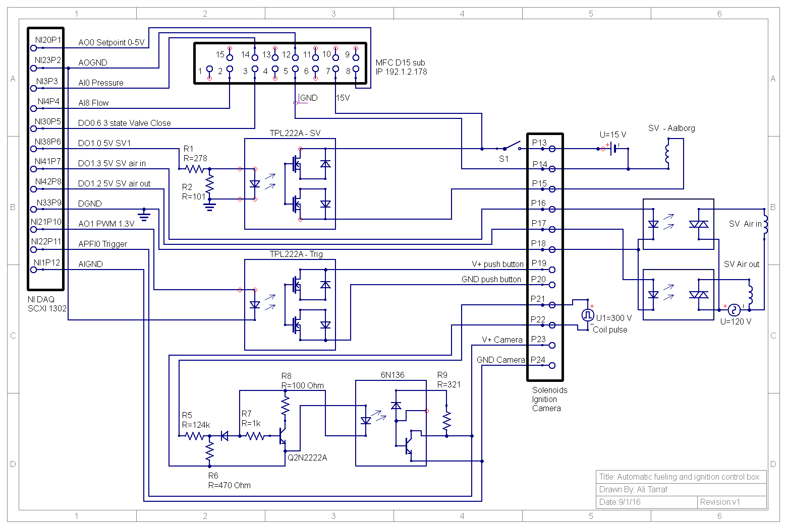
Starting with a black box and recording the inputs and outputs of the box, an electrical circuit diagram can be developed by working through each sub circuit to finally get to the final circuit diagram.

Main subsystems
- 3 Solenoid Valves to control with different working voltages (one 15VDC and two 120VAC)
- Mass flow controller requiring an analog output voltage from 0-5VDC
- Triggering of spark plug by a PWM pulse to an ignition control box
- Synchronized triggering of DAQ for pressure measurements and camera for high speed imaging
The hardest part of the circuit was to get a clean pulse out of a the ignition coil. This pulse (P21-P22) is passed through a voltage divider and transistor circuit before activating the optoisolator (6N136) to send the trigger signal to the DAQ and camera.
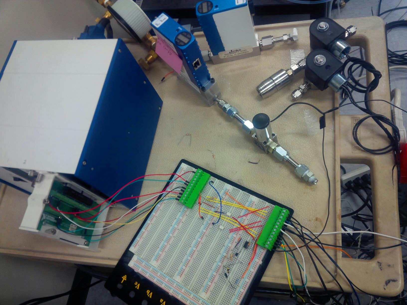
Prototype
More than 3 prototypes version of the circuit have been made and tested with incremental improvement in each version.

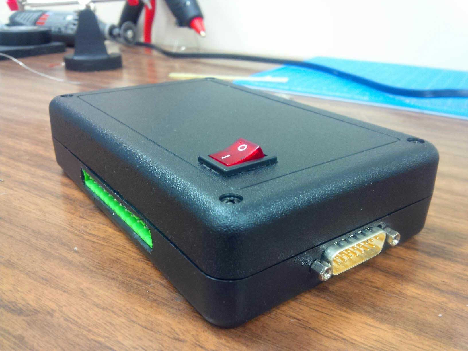
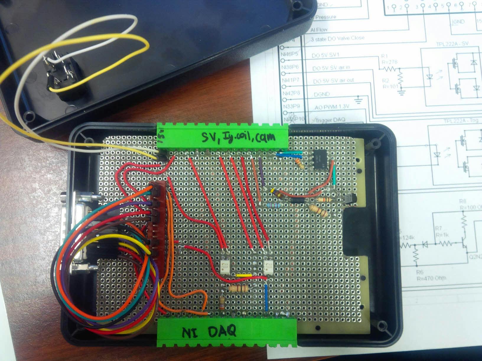
Final version
The final version of the circuit was soldered onto a perforated board and packaged in a black box with just the right size. Soldering of both sides was used to keep a the wiring as neat as possible. One problem emerged with reading of the Analog input data from the mass flow controller into the DAQ: when reading the analog voltage of the mass flow controller pressure and flow with a digital multimeter, the expected values (0-5V) are registered. But when reading the voltages with the Analog input channel of the DAQ, no voltages are registered and the DAQ seems to affect the voltage set point given to the mass flow controller for flow control.